Building a coax entry panel

Loading

Overview:

A year or so ago, I got the idea of installing a loop antenna to help reduce some of my RFI.  Not wanting to follow some of my previous bad practices with more bad practice, I decided to totally rebuild my coax entry method.  This led to the creation of a patch panel, and that in turn led to the creation of a coax entry panel for bringing coax into the home.

The Antenna farm:

Antenna FarmRight now I have a single 6BTV up, with plans for a 30 meter four square, a loop, and a 6 meter antenna of some sort.  So I needed at least three cables coming into the home.  I dislike doing things twice, and having to redo things from scratch, so I built an entry panel for six cables, each lightening arrested, and with proper grounding.


Location:

I am fortunate that my shack is about 15 feet away from the power service panel, and service ground.  That makes for a fairly easy path for grounding the station and entry panel.  I selected a NEMA 4 box, I found surplus.  Located a copper panel, and then started collecting all the parts needed to build a entry panel for coax.  First I needed a good ground, so I drove a 5/8th inch diameter ground rod below where the panel was going to live.  I did not use water, or anything else but a rod driving device I rented.  I also drove several  other rods to connect to the antenna farm later, along the coax route, and at the antenna mount points.

Antenna mount points:

Several years ago I decided to build an antenna farm, and did not want to be fighting cables, so I trenched the entire backyard, creating a tunnel system for cable distribution.  I am fortunate in that I have almost a half acre to play with for antenna use…

Grounding

Finished panel.

Finished panel.

I first decided on where I was going to bring in the coax cables into the home.  That helped me place where the entry panel would live.  I next pounded in a eight foot ground rod, directly under where the entry panel would be mounted.  I connected the new ground rod to the electrical service, via #4 bare copper wire, in order to create a single ground system for the home.  Eventually I will finish a full ground ring around the house.

The entry panel box

I scrounged a rather largish entry panel box from a friend who is in the electrical business.  There were a few holes in the bottom, but otherwise it was in good shape, and was NEMA 4 rated.  NEMA 4 keeps most water out, and is built for outdoor use.  I ordered a set of hole plugs to plug the existing holes in the box.  This gave me a water proof box I could mount outside on the house wall.

I had been saving a largish one eighth inch thick copper plate for a few years I picked up at a hamfest.  I took it to a metal shop, and had it cut to slightly smaller than the box ID.  I next drilled four holes in the copper, so as to mount it on the existing mounting lugs on the inside of the NEMA 4 box.  I sanded the top of the mounting lugs, and applied a star washer between the copper plate, and the box mounting lugs.  This connected the copper plate to the box itself, at 4 points.  That way, when I grounded the copper plate, I was also grounding the Entry Panel box.

My intent was to build up the copper plate with all the lightning arrestors, ground mounts, and anything else I needed on the copper plate, then mount the copper plate into the NEMA box, and finally mount the NEMA box on the wall of my home.  That way, I could build up everything inside, out of the weather, and near my tools…

I first purchased the lightning arrestors.  I used Alpha Delta arrestors, as they only needed a single hole for mounting, and they were substantially less expensive than other brands on the market.  I believe the Alpha Delta product does as good a job as any other arrestor, so I had no qualms about using them.  Next I laid out all the parts on the copper plate, and commenced to moving them around until I was happy with the layout.  I wanted all coax entering the box from the bottom, and in EMT conduit.

Why conduit the coax?  RFI protection.  The conduit is connected to the NEMA box, the NEMA box is connected to teh copper plate, and the copper plate is connected to a ground rid via about four feet of number six bare copper wire, and then to the electrical service, which also has a ground rod.  This places my coax inside a grounded two inch diameter metal piece of EMT pipe, as it runs into the bottom of the box.  This serves to weatherproof the connections, arrestors, copper plate, and everything else inside the NEMA box…

Back to laying out the copper plate– I next used a sharpie and added markings to the copper plate for every device I wanted to mount on the plate.  Each lightning arrestor, each ground lug, each mount point for wire ties, etc.  I took the plate to a friends place and drilled out all the holes using his drill press.

Now that all the holes were drilled, it was time to mount everything and see if it would actually fit in the NEMA box.  It did!  Next I mounted the plate in the NEMA box, and marked where the coax should enter the box from the bottom.  This completed the NEMA box portion of this project.

Water is NOT your friend

Why feed from the bottom?  Think water…  It rains a LOT where I live in Oregon, and I wanted all water to run away from the house, the box, and the coax conduit.  If you have an above ground power feed, take a look at where it enters your home.  Notice the drip loops so water is not allowed to run into your home via the power entry point, but drip off the cables into your roof, where the water is controlled, and move off the home, not into your home.  That is what I wanted as well– no vector for water to enter my home, or the NEMA box.  Everything is gravity assisted to run any water AWAY from the NEMA box, the coax conduit, and hence, my home.

Mounting the box

Entry Panel proposed diagram.I have to admit, I know very little about mounting boxes to the home, and drilling through walls to get wall plates where I want them.  Given the possible cost of a mistake, I elected to hire an electrician to mount the box, and drill the wall for the inside wall plate.  He made fairly short work of this project, and when he left I had a empty NEMA box on the wall, some EMT conduit on the wall, connected to the box, all weatherproofed, and ready for cables, and the copper plate.

Wiring the box

Now that the box was mounted on the house, I bolted the copper plate, with all the items on it, to the inside of the box.  All fit as I expected.  The ground lugs were right above the holes in the box for the gland fitting for the ground wire, and the holes for the conduit were where they were expected on the copper plate.  So I made the install of the plate permanent. Next I needed to pull some cables.  I ran a stinrg from the radio location to the lightening arrestors inside the box, via the route the cables would take from the radio to the box first.  Worked out to be eleven feet.  I next cut eleven and a half feet of RG8X, and ran that to make sure…  It was good, glad I added that extra six inches.

I pulled the cable, and then cut five more cables just like it.  I am fairly big on labeling things, so I labeled each cable with a label, and a piece of clear heat shrink over the label.  I used to work in electronics before I retired, and always labeled cables.  One of the things I learned was labels fall off after a few years.  So I started using clear heat shrink over labels, and that solved the problem.  Old habits die hard, and I still label everything, and cover the label with heat shrink…  After labeling the cables on each end, I bundled them, wire tied them, and ran them out of the shack into the junction box, and up to the NEMA box.  Why a junction box first, and not just directly into the NEMA box?  The NEMA box would have been very low on the house, so I needed to right angle the cable up to the box.  This also gave me a pull point straight out of the wall plate…  I routed the cable bundle in place in the shack, then tied it down so I could not pull it out of place.  I then pushed it through the wall and out into the open on the outside of the house.  Next I ran it up the conduct to the bottom of the NEMA box, and into the NEMA box.  I then terminated the ends of each cable with a high quality, PL-259, and routed it to the lightning arrestors.  I mounted four cable tie mounts on the copper plate prior to installing it into the box so I could create a cable run.  I ran everything in place, and added cable ties.

I was careful to observe the bend radius rules for RG-8X, plus some…  I never exceed bend radius limits for coax, that is a good way to smoke your amp, when the center conductor migrates to the shield, and provides a direct short on the coax.  If you are unfamiliar with the term “Bend Radius”, you should become familiar with it today!  I have seen far too many Amateurs ignore the bend radius rules when making chokes, and running coax.  If you ignore bend radius, you will be punished one day…  You have been warned!

I next needed to run six cables from the box to an intermediate point where my underground tunneling surfaces by the patio.  That took another six thirty or so foot runs of RG-8X, and another twelve high quality PL-259 connectors.  Those cables were labeled, and placed in an intermediate box.  All antenna run to that intermediate box, and then to the entry panel via the thirty foot EMT conduit to the entry panel.

Critter Proofing

Where we live we have a lot of rather aggressive, racoons, squirrels, and flying stinging, insects.  The stinginging insects like to build nests in everything.  Not wanting to open thge NEMA box one day to find a wasp nest, I decided to critter proof everything.  An electrician friend once taught me how to do this using Stainless Steel wool.  Note I used STAINLESS STEEL wool, not steel wool.  Normal steel wool will rust after a time, where SS wool does not.  I stuffed every entry hole in every conduit with SS wool, leaving enough to be able to remove it if need be.  I also found a plumbing pipe cover the perfectly fit two inch EMT.  I cut a small cross in it, stuffed SS wool into the EMT, then put the cover on.  That keeps out the stinging, and four legged critters out of the entry EMT.  I then added myet more SS Wool to the EMT entry points at the Entry panel as well, in the event something got past the first barrier…  Sometimes paranoia is your friend!

How does it work

Entry PanelGreat, I can add a new antenna, without ever having to crawl around, go under the house, or climb anything.  It takes only one person to connect a new antenna to the rig, and in general I am a lot happier to have things well grounded, lightening protected, and looking good…

Categories: Cleanup, Construction, Info, RFI Mitigation, Station, Tools | Leave a comment

6BTV Yearly Maintenance

Loading

Overview:

I do a yearly maintenance on my 6BTV, just before Winter starts each year.  Why?  It rains in Oregon, and it rains, and it rains…  It rains all winter.  Not hard, just a constant drizzle…  I dislike working in the rain, so once a year in August, or early September, I bring down the 6BTV, and look things over…  I thought I might share what I do for the next person… Read more »

Categories: 6BTV, Reviews, Setups | Leave a comment

Building a K4 external keypad

Loading

Overview

Protect Cover for CP-48I have a belief that the less you touch your hardware, the longer it will last, and the cleaner it will remain…  Sometimes I do contesting, and it occurs to me that during a contest, I might hit the memory button containing my callsign, several thousand times during the course of a contest.  While the button is probably rated for millions of presses, if nothing else, it will get very dirty over time, as I use it over and over…  I very much dislike that, so I developed an external keypad for my Elecraft K3.  Upon updating to the Elecraft K4, I discovered I could not live without the Genovation Keypad, I had been using for years on the K3. Read more »

Categories: Construction, Elecraft K4, Info | Leave a comment

Propagation, part II

Loading

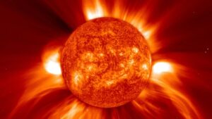
“The Sun, and the Ionosphere”


Overview
The Sun, image credit: NASA, GSFC, SOHO, ESA

The Sun, image credit: NASA, GSFC, SOHO, ESA

The sun is a gigantic, continuously running nuclear fusion reactor, 93 million miles away.  It is so far away it takes the light from the sun eight plus minutes to reach Earth.  Yet, that light from the sun can still cook the skin right off your shoulders if you are not wearing sunscreen.  That energy also can create complex chemical reactions in the ionosphere, that allow radio waves to be refracted, absorbed, or passed, thus allowing us to work DX, or closing the bands.  Clearly the sun is delivering quite a large energy punch to the earth’s upper atmosphere, and just as clearly that energy punch is changing how the ionosphere refracts radio waves. Read more »

Categories: Propagation | Leave a comment

Propagation Part I

Loading

The Ionosphere

Overview

This is the first in a multi part set of articles that will help you understand how to work more DX by understand band openings, and band closings.  In order to work more DX you will need to understand what bands are open, when they are open or closed, and, if they are open, where they are open to.  That said, let’s get started, in this first article, atmospheric, and ionospheric structure will be covered.  That will give you the basis for understanding how, and why, DX comes about.  What you learn today, will be useful tomorrow, and in understand the rest of this series.  Throughout this series of articles, you will see links to other articles, and web pages.  These links are to assist you in learning more if you want.  You do not need to follow these links to understand what this series of articles is trying to teach. Read more »

Categories: Education, Propagation | Leave a comment

Notes: tinySA

Loading

tinySA device, click to enlarge.

Overview:

Having just purchased a tinySA, I went through the upgrade, and tools location process one does with every new piece of hardware.  I thought it might be a good idea to document the steps I used to process this item into my lab, so I thoughts I’d make a few notes on setting up the tinySA for the next person…  This is not a review, it is a few notes I might need later on to reinstall it from scratch, and  I thought I might share them with you!

I have always wanted a spectrum analyzer, I have looked at the multi thousand dollar ones for decades.  Not having several thousand bucks in throw away, I bought a used ATTA spectrum analyzed for $65.00 several years ago.  It does the job, not as well as a good HP, but it does OK for my needs.

I still want the expensive HP type of Spectrum Analyzer, but alas, I doubt I will have $45,000 bucks to throw at it.  When I saw the “tinySA”, (tiny spectrum analyzer), come to market a few months ago, and saw that R&L was selling them for $54.98, I just had to have one…  Not that the tinySA will replace a $45,000 spectrum analyzer but it does the job I need, and for $50.00 I am happy as I could be with it. Read more »

Categories: Accessories reviews, Direction Finding, Info, Notes, Quantification, RFI Mitigation, RFI Signatures, Setups, TinySA, Tools | 11 Comments

Review of DX Engineering’s 6BTV 17 Meter add on kit

Loading

Add on kit Instruction cover sheet

Overview:

Over the past few years I have been using a Hustler 6BTV vertical antenna as my primary antenna for 80, 40, 30, 20, 15, and 10 Meters.  The antenna has worked very well for me, and I have worked much DX with it.  Over the years I have spent a great deal of time getting things tuned as I want them, putting a large, (40 radials), radial field in place, and getting the antenna exactly the way I want it.

I have been using a BWD-90 for 60, 17, and 12 meters.  The BWD-90 is basically a Dummy Load you suspend in the air, then feed it power.  Some of that power leaks out and is radiated, the rest goes up as heat.  The BWD-90 is about 6 db down from a dipole performance wise.  You might ask yourself why in the world would anyone use a BWD-90?  The answer is it is flat across the 3-30 MHz., spectrum at under 2:1 SWR.

As you can guess, the BWD-90 is not a  stellar performer, but it will load on almost any frequency.  I have been on a station simplification quest now for a few years, removing equipment where I can, and in general reducing the complexity of my station.

Part of that quest was to try DX Engineering’s DXE-A0KB-17M-INS 0c, 17 meter add on kit for the Hustler 6BTV.  I have had a lot of trepidation with regards to making any change to the 6BTV, as it is working very well, and I want it to continue that way.  I have literally spent years, tuning and setting this antenna and its associated radial field up.  As a result of all that work, and time spent, I don’t want anything to mess with the performance of the 6BTV.  I was quite worried about what would happen to the antennas performance if I added the kit. Read more »

Categories: 6BTV, Antenna Reviews, Construction, DX, Info, Reviews | 3 Comments

KPA500 Input vs. Output Power

Loading

Elecraft KPA500 AmplifierHaving just purchased a KPA500 amplifier by Elecraft, I thought it might be a good idea to characterize a few important things about the amp.  One being the input vs. output power levels.  I had occasion to send the amp to Elecraft for testing, and updating.  The amp has been recently returned, as up to specs by Elecraft.

The amp was fed into a KAT500 tuner, and an actual antenna was tuned and used for all tests, save 30 Meters.  A dummy load was used for all 30 Meter testing.

The power on each band was increased in small steps while the output power was entered into a spreadsheet.  I used the spreadsheet to graph the amp in/out ratios.  Below you will find the input vs. output graphs for my KPA500.  This dataset is not designed to show the 1 db compression points, just a general feel for how the amp should behave.

Raw spreadsheet here… Read more »

Categories: Elecraft K3, Info, Reviews | Leave a comment

Elecraft K3: KSYN3A synthesizer installation notes

Loading

Elecraft K3

Elecraft K3

Overview:

At one point, myself and K7OLN were living about 700 feet apart.  Both of us were very active, and as a result could not operate on the same band at the same time.  I purchased an Elecraft K3, and that helped, K7OLN then purchased a K3 and that helped more.  Then Elecraft came out with a low phase noise synthesizer, the KSYN3A.  This helped a lot.  As it turns out I was able to document the changes as we each added the new sensitizer boards to our radios.  This set of notes contains a set of images that were taken shortly after Elecraft made the new synthesizer available, and as we made the changes to each K3.

Setup:

Two K3s were used in this test and the old synthesizers were replaced in stages.  The K3s were separated by approximately seven hundred feet, both feeding resonant antenna, and both running approximately 50 watts each when tested.  K3 A, was owned by NK7Z, and K3 B, was owned by K7OLN.  Both started with the old synthesizer in place.

Results: Read more »

Categories: Cleanup, Elecraft K3, Info, Setups | 2 Comments

RFI Site survey – Part II, interpretation

Loading

Overview:

Annotated 40 meters showing various RFI events

Annotated 40 meters showing various RFI events

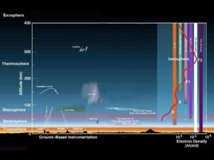
This is part II in a series of articles which will cover how I interpret and use SDR captured spectrograms as they relate to my RFI mitigation efforts.  See Part I, Using a SDR as a Site Survey Tool for how I setup and use the SDRPlay RSP1 as my SDR of choice, while using HDSDR as the radio control program.  The concept was to view my RFI environment as a whole, not in real time, but across long periods of time, and very wide frequency spans.  Once you have looked over part I, and part II, take a look at the RFI Samples page.  This page presents various forms of RFI so you might be able to tell what is causing your RFI issues.

Real world examples of RFI will be used here showing how I can infer what appear to be disparate RFI sources, as related sources.  Part I covered my choice, installation and setup of HDSDR, and an SDRPlay RSP1 SDR for use as a site survey tool. Read more »

Categories: Education, I have RFI: Series, Info, RFI Mitigation, SDR as Site Survey tool | 1 Comment